Assembling Your Picture Frame
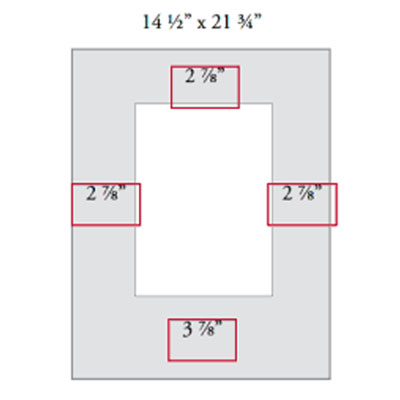
After you've prepared your materials to be worked with, it's time to fashion them into something that can be used. For matting this means cutting a window in the mat blank you've made from the larger sheet. For framing this means taking the frame sections you've cut from the longer sticks and assembling them into an actual frame by joining them at the corners.
Logan offers two joiners for joining picture frame mouldings: The Studio Joiner F300-1 clamps the moulding in a standard clamp (included) and presses one V-nail at a time into the back of the frame with the moulding lying face down. The Pro Joiner F300-2 clamps the frame in a sophisticated vise and drives two V-nails up from underneath with the moulding lying face up. The less expensive Studio Joiner requires that you level the frame using the spacer included and that you visually line up the nails before driving. The Pro Joiner levels and aligns the moulding for you, making the process quicker and more precise.
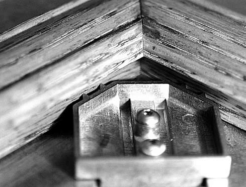
A "V-nail" is a V-shaped staple designed to penetrate wood with one wing on either side of the joint where the mitered ends of two frame sections form a corner (Figure I-1). V-nailing is preferred over traditional nailing because the nail is driven into the back of the moulding rather than the side, making it less conspicuous and avoiding the need to cosmetically cover up the nail head.
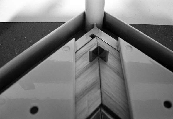
penetrates the wood on either side of the miter
Joining with the Studio Joiner F300-1:
Step One: Begin by selecting the correct V-nail for the job. V-nails commonly come in two types (hardwood or soft/medium wood) and four sizes (1⁄4 ", 3⁄8 ", 1⁄2 " or 5⁄8 "). Hardwood V-nails are often red along the cutting edge while soft/medium V-nails are often white along the cutting edge. Hardwood V‑nails should be used for very hard woods like oak, hickory and maple. Soft/medium wood V-nails should be used for most other types of moulding, including pine and basswood. The size of the V-nail indicates the depth to which the V-nail will sink, not the width across its wings. Choose a V-nail that is slightly more than half the thickness of the moulding. For example, if you have a moulding that measures 3⁄4 " thick, a 1⁄2 " V-nail would be best. Plan on using two V-nails per joint unless the frame is very narrow, in which case one will suffice.
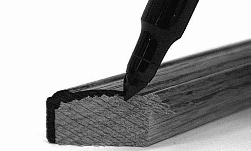
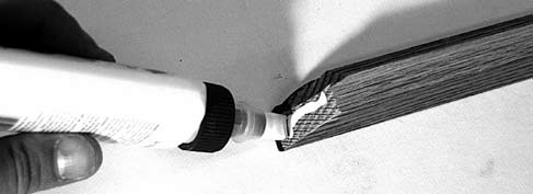
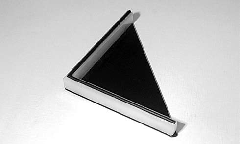
Step Two: If you wish, before clamping the moulding, you can mark the edge of each miter with a stain pencil to disguise any gap at the joint and render the seam inconspicuous (Figure I‑2). The corners of frames joined by V-nails can also be reinforced with wood glue. If you wish, place a small bead of wood glue on the miter face of one section and spread it evenly over the miter before clamping (Figure I‑3).
Step Three: Select two moulding sections to join. Unless the frame is square-shaped, this means one section will be longer than the other. Put the longer section on the right and shorter section on the left as you place them in the clamp.
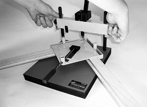
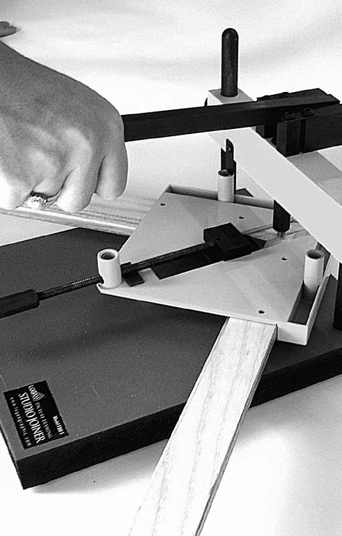
Step Four: Place the two sections face up in the clamp. Bring the two miters into contact with each other. Press the spring button and slide the clamp handle forward, trapping the two sections (Figure I‑4). Using a soft cloth, wipe away any excess glue that squeezes out of the seam.
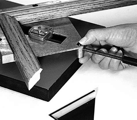
Step Five: Loosen the clamp slightly and adjust the joint so the two miters are aligned, making a perfect corner (Figure I‑5). Re-tighten the clamp firmly.
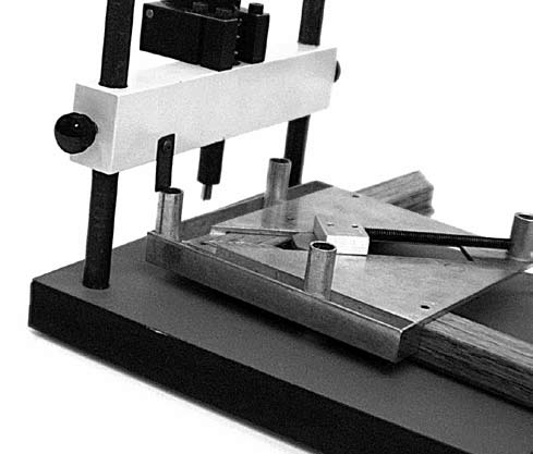
Step Six: Adjust for depth of penetration. Loosen the knob on the beam and raise the beam so the clamped moulding will fit underneath (Figure I‑6). The clamp has posts on the bottom that stick up. With the clamped moulding under the beam, lower the beam until the depth gauge touches the top of one of the posts (Figure I‑7). Then tighten the knobs, fixing the beam in place. The depth gauge may be pivoted out of the way for added clearance.
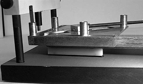
Step Seven: Determine whether or not to use the spacer. Mouldings likely to tip or rock when lying face down will need the spacer to level and support them (Figure I‑8). With the clamped moulding face down, insert the spacer between the moulding and the base if necessary (Figure I‑9).
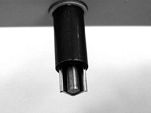
Step Eight: Load a V-nail. Hardwood V-nails are red along the cutting edge while soft/medium V‑nails are white along the cutting edge. The colored edge is the sharp edge. It is important that the V-nail be driven with the cutting edge against the wood. Driving a V-nail upside down will cause it to jam and crumple. Insert the V‑nail around the magnetic tip with the sharp edge of the V-nail facing down. (Figure I‑10).
Step Nine: Visually align the penetration point of the V-nail. Place the first V-nail about a quarter inch in from the rabbet. Place the second V-nail about halfway between the first V-nail and the perimeter of the frame (Figure I‑11). The wings of the V-nail should penetrate uniformly on either side of the joint as the lever is pulled down.
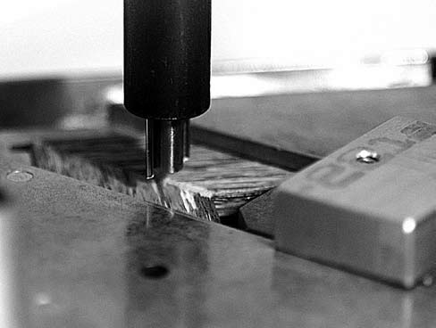
Step Ten: Press down on the lever, driving the V‑nail into the wood (Figure I‑12). Press until the bottom of the V-nail is flush with the surface of the wood. Repeat for the second V-nail on the same corner.
Repeat for the remaining three corners of the frame. Be careful when assembling the remaining sides. Instead of adding another section to the sections already joined, join the remaining two sections next. If you started by placing the long length on the righthand side of the vise, then the second half of the frame must also be joined by placing the long length on the righthand side of the vise, thereby giving you two identical halves of a frame which can be correctly joined together.