Joining with the Pro Joiner F300-2
Step One:
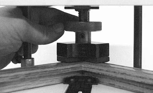
The clamp moves up and down for an adjustable height relative to the base of the joiner. Lock the clamp at a level that's easy to work with using the "clamp locking lever" (Figure J‑1).
 Step Two:
Select two moulding sections to join. Unless the frame is square-shaped, this means one section will be longer than the other. Plan on putting the longer section on the right and shorter section on the left when you place them in the clamp.
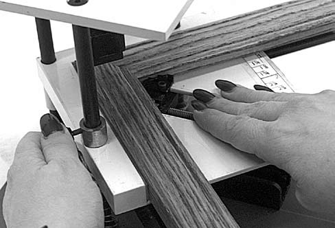
Before putting the sections in the clamp you may wish to mark the edge of each miter with a stain pencil to disguise any gap at the joint and render the seam inconspicuous. Glue the sections before clamping. The corners of frames joined by V-nails are typically reinforced with wood glue. Place a small bead of wood glue on the miter face of one section and spread it evenly. Place the two sections of moulding face up in the clamp. Bring the two miters into contact with each other. Press the spring button and slide the clamp jaw forward, trapping the two sections (Figure J‑2).
Step Two:
Select two moulding sections to join. Unless the frame is square-shaped, this means one section will be longer than the other. Plan on putting the longer section on the right and shorter section on the left when you place them in the clamp.
Before putting the sections in the clamp you may wish to mark the edge of each miter with a stain pencil to disguise any gap at the joint and render the seam inconspicuous. Glue the sections before clamping. The corners of frames joined by V-nails are typically reinforced with wood glue. Place a small bead of wood glue on the miter face of one section and spread it evenly. Place the two sections of moulding face up in the clamp. Bring the two miters into contact with each other. Press the spring button and slide the clamp jaw forward, trapping the two sections (Figure J‑2).
 Step Three:
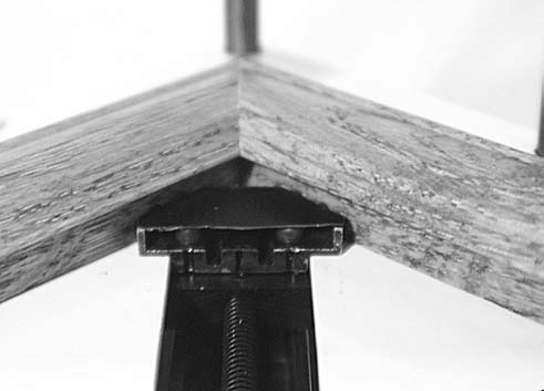
It's important to align the joint properly in the clamp. Loosen the clamp slightly and adjust the sections so the top corner of the joint is square (Figure J‑3). Then re-tighten the clamp firmly.
Step Three:
It's important to align the joint properly in the clamp. Loosen the clamp slightly and adjust the sections so the top corner of the joint is square (Figure J‑3). Then re-tighten the clamp firmly.
 Step Four:
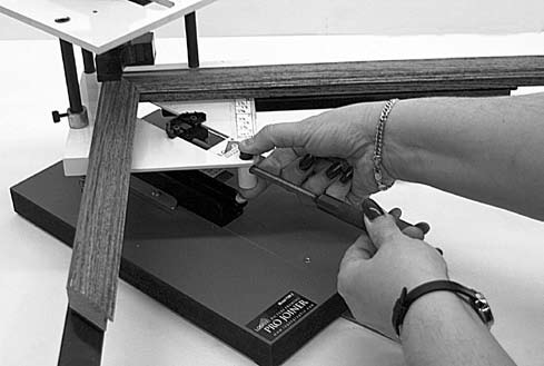
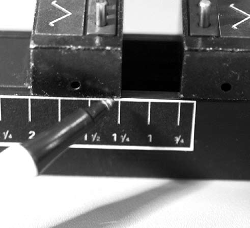
Adjust the position of the V-nails. First, measure the width of the moulding using the "set block scale" on the clamp (Figure J‑4).
Step Four:
Adjust the position of the V-nails. First, measure the width of the moulding using the "set block scale" on the clamp (Figure J‑4).
![Figure J-4: Measure the width of the moulding using the]() block scale" on the clamp." src="//www.logangraphic.com/i/legacy/joining-with-the-pro-joiner-f300-1-4.png">
Step Five:
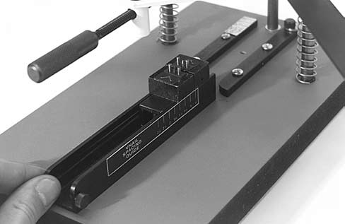
Next, working from the measurement determined on the "set block scale", adjust the V‑nail blocks on the cartridge to that measurement (Figure J‑5). Do not load the V-nails yet. First, you must adjust the range of the press.
block scale" on the clamp." src="//www.logangraphic.com/i/legacy/joining-with-the-pro-joiner-f300-1-4.png">
Step Five:
Next, working from the measurement determined on the "set block scale", adjust the V‑nail blocks on the cartridge to that measurement (Figure J‑5). Do not load the V-nails yet. First, you must adjust the range of the press.
 Step Six:
To adjust the range of the press, release the clamp locking screw and adjust the foot screw until the foot contacts the face of the moulding (Figure J‑6).
Step Six:
To adjust the range of the press, release the clamp locking screw and adjust the foot screw until the foot contacts the face of the moulding (Figure J‑6).
 Step Seven:
Slide the V-nail block cartridge (without the V-nails loaded) between the guides. Slide it back until it stops (Figure J‑7).
Step Seven:
Slide the V-nail block cartridge (without the V-nails loaded) between the guides. Slide it back until it stops (Figure J‑7).
 Step Eight:
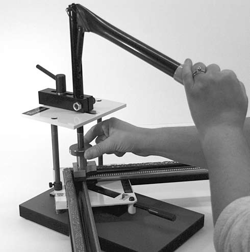
Lower the lever arm and make minor adjustments to the foot level by turning the foot screw (Figure J‑8). Keep adjusting until the moulding bottoms out on the V-nail blocks when the lever arm is fully lowered. You will feel the lever arm notch and lock as it bottoms out. The range of the press is now adjusted and you are ready to load the V-nails.
Step Eight:
Lower the lever arm and make minor adjustments to the foot level by turning the foot screw (Figure J‑8). Keep adjusting until the moulding bottoms out on the V-nail blocks when the lever arm is fully lowered. You will feel the lever arm notch and lock as it bottoms out. The range of the press is now adjusted and you are ready to load the V-nails.
 Step Nine:
Raise the lever arm and remove the V‑nail block cartridge. Load the V-nails onto the blocks. Make sure the sharp edge of each V-nail is up. It's important that the V-nail is driven with the cutting edge against the wood. Driving a V-nail upside down will cause it to jam and crumple. Small diagrams on the blocks will show you the proper arrangement of the V-nails on the pins (Figure J‑9).
Step Nine:
Raise the lever arm and remove the V‑nail block cartridge. Load the V-nails onto the blocks. Make sure the sharp edge of each V-nail is up. It's important that the V-nail is driven with the cutting edge against the wood. Driving a V-nail upside down will cause it to jam and crumple. Small diagrams on the blocks will show you the proper arrangement of the V-nails on the pins (Figure J‑9).
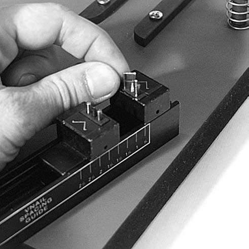

Figure J-1: Lock the clamp using "clamp locking collar" at a level
that's easy to work with.
that's easy to work with.

Figure J-2: Adjust the clamp jaw by pressing the spring button
and sliding the handle until the moulding is secure.
and sliding the handle until the moulding is secure.

Figure J-3: Adjust the moulding sections in the clamp so the top
corner is square.
corner is square.
Figure J-4: Measure the width of the moulding using the "set
block scale" on the clamp.
block scale" on the clamp.

Figure J-5: Adjust the V-nail blocks to the measurement
determined on the set block scale.
determined on the set block scale.

Figure J-6: Release the clamp locking screw (not shown) and
adjust the foot until it contacts the moulding.
adjust the foot until it contacts the moulding.

Figure J-7: Slide the V-nail block cartridge (without the V-nails
loaded) between the guides. Slide it back until it stops.
loaded) between the guides. Slide it back until it stops.

Figure J-8: Lower the lever arm and make minor adjustments to
the foot level until the moulding bottoms out on the V-nail blocks.
the foot level until the moulding bottoms out on the V-nail blocks.

Figure J-9: Remove the V-nail block cartridge and load V-nails
onto the V-nail blocks.
onto the V-nail blocks.